SMART LATCHING RELAY CONTROL
Description
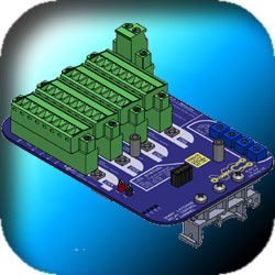
The WMC SLRC-4 is a programable IO module purpose built to interface an ID badge reader, specifically the LNL-1320 with machine shop equipment to allow employees to badge into equipment they are authorized to use. It is designed to support 4 pieces of equipment with ID Badge readers.
Operation Overview
The dry contact on the badge reader or other triggering device is wired into the enable channel input to activate the channel. Activating the channel will allow the equipment to be powered on, and starting an internal timer. If the machine is running the current flowing to the equipment will close the current switch wired to the timer hold/reset input (In 2). Running the piece of equipment will reset and hold the timer allowing the equipment to continue running. Once the machine is no longer being used causing current to stop flowing and the current switch to open, the SLRC-4 will start timing down on that channel. Once the timer has elapsed it will open the latching relay disabling the equipment until a valid badge is scanned again. The PNP output is used to drive an alarm signal at the piece of equipment. If the channel timer has less than 3 minutes remaining it will pulse the PNP output once every 16 seconds. Once the channel has less than 1 minute remaining the PNP output is held on continuously. When the channel is disabled the PNP output is off.
Custom Firmware
Firmware can be custom programmed to support any customer requirement utilizing the full set of I/O available to the SLRC-4. This allows the device to be an 8 Input, 8 Output, 4 Latching Relay module, it is not limited to being "4 channels" this is just the default behavior.
The Expansion Interface Module provides 4 channels of bi-directional communication to smart remote modules. These remote modules provide Information feedback and operator input capabilities at the piece of equipment. For example a supervisor key to override the channel, a status light, or up to a full operator interface controlling all 4 channels. The system can be programmed to trigger or modify any channel or combination of channels from these remote modules.
- 2A Relay Contacts
- PNP Out
- 24V In
- Expansion Interface
- Custom Firmware
Four latching relay contacts, rated at 2 Amps, are available, one per channel plug. This allows the board to enable the Piece of equipment even in the event of a power failure at the SLRC board.
On power up the SLRC reads back the state of the latching relays to determing if they were set or reset when power was lost.
Four PNP Outputs are available, rated at 2 Amps, one per channel plug. Used in the default behavior profile to signal when the timer is close to timing out so the user can reauthorize more time.
24V Inputs used to enable the channel, and reset / hold the timer so the Field device remains enabled.
An Expansion Interface Module is available to allow field devices to communicate serially with the SLRC-4 board greatly expanding its capabilities and responsiveness. The field modules can be as simple as pushbuttons, or as complicated as Ethernet hubs and HMI screens. Any combination of devices can be combined to form a working system.
The SLRC 4 can be programmed via the 20 Pin programming header to any behavior the customer desires, running a MSP430g2553 processor from TI the processor can run any custom code to be written for it. The units 8 Outputs, and 8 Inputs can be combined in any configuration required. Rather than being set to 4 identical channels.
contact WMC with requirements.